IPSEC – Freebsd (StrongSwan) – Cisco IOS-XE – VTI & IKEv2/PSK

Router configuration

Cisco IOS XE Software, Version 17.03.04a
cisco CSR1000V (VXE) processor (revision VXE) with 2071829K/3075K bytes of memory.
Processor board ID 9WL1PRT9H0W
Router operating mode: Autonomous
4 Gigabit Ethernet interfaces
32768K bytes of non-volatile configuration memory.
3978432K bytes of physical memory.
6188032K bytes of virtual hard disk at bootflash:.
crypto ikev2 keyring CRYPTO-IKEv2-KEYRING-01
 peer <freebsd-name>
  address <freebsd-ip>
  identity fqdn <freebsd-name>
  pre-shared-key <psk>
crypto ikev2 profile CRYPTO-IKEv2-PROFILE-02
 match identity remote address <freebsd-ip> 255.255.255.255
 match identity remote fqdn <freebsd-name>
 identity local fqdn <router-name>
 authentication remote pre-share
 authentication local pre-share
 keyring local CRYPTO-IKEv2-KEYRING-01
crypto ipsec transform-set CRYPTO-IPSEC-TS-01-TUN esp-aes 256 esp-sha256-hmac
 mode tunnel
crypto ipsec profile CRYPTO-IPSEC-PROFILE-02
 set transform-set CRYPTO-IPSEC-TS-01-TUN
crypto ikev2 nat keepalive 30
crypto ikev2 dpd 10 2 periodic
interface Tunnel0
 ip address <tunnel-net>.1 255.255.255.252
 ip mtu 1400
 tunnel source <router-IP>
 tunnel mode ipsec ipv4
 tunnel destination <freebsd-ip>
 tunnel protection ipsec profile CRYPTO-IPSEC-PROFILE-02 ikev2-profile CRYPTO-IKEv2-PROFILE-02

FreeBSD/StrongSwan configuration

# /etc/rc.conf
ifconfig_vtnet0="inet <freenbsd-ip>/<freebsd-mask>"
defaultrouter="<freebsd-gateway>"
strongswan_enable="YES"
# /usr/local/etc/strongswan.conf
charon {
        install_routes = no
}
# /usr/local/etc/strongswan.d/ike-updown
case "$PLUTO_VERB:$1" in
up-client:)
        if [ ${PLUTO_CONNECTION} = "<router-name>-vti-tunnel" ]
        then
                if_name=ipsec0
                ifconfig $if_name create >/dev/null 2>&1
                ifconfig $if_name reqid ${PLUTO_REQID}
                ifconfig $if_name inet tunnel ${PLUTO_ME} ${PLUTO_PEER}
                ifconfig $if_name inet <tunnel-net>.2/30 <tunnel-net>.1
        fi
        if [ $VPN_LOGGING ]
        then
                logger -t $TAG -p $FAC_PRIO \
                        "+++ ${PLUTO_CONNECTION} - ${PLUTO_REQID} - ${PLUTO_ME} (${PLUTO_MY_ID}) -- ${PLUTO_PEER} (${PLUTO_PEER_ID})"
        fi
        ;;
down-client:)
        if [ ${PLUTO_CONNECTION} = "<router-name>-vti-tunnel" ]
        then
                if_name=ipsec0
                ifconfig $if_name down >/dev/null 2>&1
        fi
        if [ $VPN_LOGGING ]
        then
                logger -t $TAG -p $FAC_PRIO -- \
                        "--- ${PLUTO_CONNECTION} - ${PLUTO_REQID} - ${PLUTO_ME} (${PLUTO_MY_ID}) -- ${PLUTO_PEER} (${PLUTO_PEER_ID})"
        fi
        ;;
# /usr/local/etc/swanctl/conf.d/router-vti.conf
connections {
        <router-name>-vti {
                keyingtries=0
                rekey_time=1h
                version=2
                remote_addrs=%any
                local_addrs=<freebsd-ip>
                children {
                        <router-name>-vti-tunnel {
                                mode=tunnel
                                policies=no
                                life_time=3600s
                                start_action=none
                                local_ts=%any
                                remote_ts=%any
                                updown = /usr/local/etc/strongswan.d/ike-updown
#                               reqid=100
                                local_ts  = 0.0.0.0/0
                                remote_ts = 0.0.0.0/0
                        }

                }
                local {
                        auth = psk
                        id = "<freebsd-name>"
                }
                remote {
                        auth = psk
                        id = "<router-mame>"
                }
        }
}

secrets {
        ike-<router-name> {
                id-fqdn-<router-name> = "<router-name>"
                secret = "<psk>"
        }
}
Posted in Uncategorized | Leave a comment

JunOS and SNMPv3 into VRFs and Logical Systems

Without addition configuration, SNMP elements that lie without the scope of the base logical system and default routing instance (aka master) are not visible to SNMP agents. This means routes, BGP neighbours, etc that are configured in routing instances and logical systems are not accessible.

To make these elements accessible to SNMP agents, a non-default SNMPv3 context must be created that refers to the LSYS and/or instance that is to be exposed. To expose the default/master instance of a logical system:

set snmp v3 vacm access group <snmpv3Group> context-prefix <lsys>/default security-model usm security-level privacy <read-view|write-view> <snmpView>

To expose a VRF/routing instance of the base LSYS:

set snmp v3 vacm access group <snmpv3Group> context-prefix <routingInstance> security-model usm security-level privacy <read-view|write-view> <snmpView>

To expose a VRF/routing instance of an LSYS:

set snmp v3 vacm access group <snmpv3Group> context-prefix <lsys>/<routingInstance> security-model usm security-level privacy <read-view|write-view> <snmpView>

To access these contexts with UCD’s snmp utilities you must specify a context with the `-n’ option:

$ snmpwalk -v3 -l authPriv -u '<user>' -a SHA -A '<authPassword>' -x AES128 -X '<privacyPassword>' -n '<lsys>/<routingInstance>' <host> <oid>

For example:

$ snmpwalk -v3 -l authPriv -u '<user>' -a SHA -A '<authPassword>' -x AES128 -X '<privacyPassword>' -n 'LSYS-TEST/RI-TEST' <host> ipCidrRouteDest
IP-FORWARD-MIB::ipCidrRouteDest.100.1.1.2.255.255.255.255.0.0.0.0.0 = IpAddress: 100.1.1.2

While I’ve not configured anything similar for SNMP v2c, I believe the same functionality can be attained by combining the context with the community with the `@’ sign. Or something like that.

Posted in Uncategorized | Tagged , , , , , | Leave a comment

10G Ethernet NIC in a HP Microserver N40L

I’m thinking of moving my storage for my NAS (N40L) from DAS to iSCSI. My current set-up is trivial (and not performant): the N40L has 4 local SATA drives and an LSI2008 in IT mode connected to 6 SATA drives.

I think the current bottleneck is the controller:

# dd if=/dev/zero of=a bs=8192 count=1310720
1310720+0 records in
1310720+0 records out
10737418240 bytes transferred in 68.962335 secs (155699749 bytes/sec)

These results are targeting the 6 drives in a ZFS RAIDZ pool.

Anyway, by moving the pool to iSCSI I will be introducing IP and Ethernet to the transport, with 10G Ethernet a must. As a quick test I installed a cheap Intel 10G NIC into a spare N40L and connected it directly to a Cisco UCS with 10G with a twinax cable. I booted both machines from live USB OSes: FreeBSD 13 on the N40L and Ubuntu 20 Server on the UCS. FreeBSD 10 would hang at random times with the 10G NIC installed in the N40L nor would it recognise the Cisco 10G NIC in the UCS,

I installed iPerf3 on each machine, bumped the MTU on FreeBSD to 9000 (crazy that it defaults to 1500 for a 10G NIC) and ran a quick test. Here’s the results:

N40L:

root@:~ # iperf3 -s
-----------------------------------------------------------
Server listening on 5201 (test #1)
-----------------------------------------------------------
Accepted connection from 10.30.1.1, port 56382
[  5] local 10.30.1.2 port 5201 connected to 10.30.1.1 port 56384
[ ID] Interval           Transfer     Bitrate
[  5]   0.00-1.00   sec  1.15 GBytes  9.89 Gbits/sec
[  5]   1.00-2.00   sec  1.15 GBytes  9.90 Gbits/sec
[  5]   2.00-3.00   sec  1.15 GBytes  9.90 Gbits/sec
[  5]   3.00-4.00   sec  1.15 GBytes  9.90 Gbits/sec
[  5]   4.00-5.00   sec  1.15 GBytes  9.90 Gbits/sec
[  5]   5.00-6.00   sec  1.15 GBytes  9.89 Gbits/sec
[  5]   6.00-7.00   sec  1.15 GBytes  9.90 Gbits/sec
[  5]   7.00-8.00   sec  1.15 GBytes  9.90 Gbits/sec
[  5]   8.00-9.00   sec  1.15 GBytes  9.90 Gbits/sec
[  5]   9.00-10.00  sec  1.15 GBytes  9.90 Gbits/sec
[  5]  10.00-10.00  sec  1.32 MBytes  9.49 Gbits/sec
- - - - - - - - - - - - - - - - - - - - - - - - -
[ ID] Interval           Transfer     Bitrate
[  5]   0.00-10.00  sec  11.5 GBytes  9.89 Gbits/sec                  receiver

UCS:

root@ubuntu-server:~# iperf3 -c 10.30.1.2
Connecting to host 10.30.1.2, port 5201
[  5] local 10.30.1.1 port 56384 connected to 10.30.1.2 port 5201
[ ID] Interval           Transfer     Bitrate         Retr  Cwnd
[  5]   0.00-1.00   sec  1.15 GBytes  9.91 Gbits/sec    0   1.39 MBytes
[  5]   1.00-2.00   sec  1.15 GBytes  9.90 Gbits/sec    0   1.39 MBytes
[  5]   2.00-3.00   sec  1.15 GBytes  9.90 Gbits/sec    0   1.39 MBytes
[  5]   3.00-4.00   sec  1.15 GBytes  9.89 Gbits/sec    0   1.39 MBytes
[  5]   4.00-5.00   sec  1.15 GBytes  9.90 Gbits/sec    0   1.39 MBytes
[  5]   5.00-6.00   sec  1.15 GBytes  9.90 Gbits/sec    0   1.39 MBytes
[  5]   6.00-7.00   sec  1.15 GBytes  9.89 Gbits/sec    0   1.39 MBytes
[  5]   7.00-8.00   sec  1.15 GBytes  9.90 Gbits/sec    0   1.39 MBytes
[  5]   8.00-9.00   sec  1.15 GBytes  9.90 Gbits/sec    0   1.39 MBytes
[  5]   9.00-10.00  sec  1.15 GBytes  9.90 Gbits/sec    0   1.39 MBytes
- - - - - - - - - - - - - - - - - - - - - - - - -
[ ID] Interval           Transfer     Bitrate         Retr
[  5]   0.00-10.00  sec  11.5 GBytes  9.90 Gbits/sec    0             sender
[  5]   0.00-10.00  sec  11.5 GBytes  9.89 Gbits/sec                  receiver

iperf Done.

When reversing the direction the results were the same.

A bit later I ran some more tests. This time iSCSI with the target being the UCS server and the initiator being the N40L. The UCS is running ESXi 6.7 passing through the HBA to a FreeBSD 13.1 VM:
mpt0 Adapter:
Board Name: SAS3444
Board Assembly:
Chip Name: C1068E
Chip Revision: UNUSED
RAID Levels: none

The 10Gb adapter in the UCS is owned by ESXi and the VM is connected using a standard vSwitch. The N40L (also running FreeBSD 13.1) has an Intel 10Gb NIC. Both NICs are configured for 9000B MTU (verified during tests with tcpdump).

Here are some raw network tests similar to those above. The UDP results require further examination.

VM -> N40L (TCP)
[ ID] Interval Transfer Bitrate Jitter Lost/Total Datagrams
[ 5] 0.00-10.00 sec 11.5 GBytes 9.89 Gbits/sec 0 sender
[ 5] 0.00-10.00 sec 11.5 GBytes 9.88 Gbits/sec receiver

VM -> N40L (UDP)
[ ID] Interval Transfer Bitrate Jitter Lost/Total Datagrams
[ 5] 0.00-10.00 sec 9.31 GBytes 8.00 Gbits/sec 0.000 ms 0/1115968 (0%) sender
[ 5] 0.00-10.00 sec 7.85 GBytes 6.74 Gbits/sec 0.007 ms 174995/1115968 (16%) receiver

N40L -> VM (TCP)
[ ID] Interval Transfer Bitrate Jitter Lost/Total Datagrams
[ 5] 0.00-10.00 sec 11.4 GBytes 9.81 Gbits/sec 0 sender
[ 5] 0.00-10.00 sec 11.4 GBytes 9.82 Gbits/sec receiver

N40L -> VM (UDP)
[ ID] Interval Transfer Bitrate Jitter Lost/Total Datagrams
[ 5] 0.00-10.00 sec 7.37 GBytes 6.33 Gbits/sec 0.000 ms 0/883094 (0%) sender
[ 5] 0.00-10.00 sec 2.68 GBytes 2.30 Gbits/sec 0.014 ms 562078/883064 (64%) receiver

Here is the VM writing to a 7K SAS drive on the HBA locally (no network involved):

dd if=/dev/zero of=/mnt/a bs=8192 count=1310720
1310720+0 records in
1310720+0 records out
10737418240 bytes transferred in 59.083653 secs (181732472 bytes/sec)

That’s a write speed of about 1.35GB/s. So we know the VM can access its local drives at that speed. I was hoping N40L hitting the same drive over iSCSI would get similar results:

dd if=/dev/zero of=/mnt/a bs=8192 count=1310720
1310720+0 records in
1310720+0 records out
10737418240 bytes transferred in 108.958877 secs (98545603 bytes/sec)

Unfortunately not. The write speeds over iSCSI were almost half of the local write speeds, 751MB/s.

When I get the time I will move the HBA to the N40L and test the local write speeds on that machine.

Posted in Uncategorized | Leave a comment

Juniper MX10003: Port speeds and ASICs

Each MX10003 comes with two MPC slots, each with two MIC slots. One slot is pre-populated with a fixed, 6-port PIC, while the other slot is free to accept a MIC. Keen-eyed readers will point out that a PIC goes into a FPC, and Juniper certainly don’t make life easy with their terminology. What the marketing team calls an MPC the Junos team calls an FPC; the same applying to MIC and PIC. These interpretations may not be perfect but will serve for this article. From here on I will be using the FPC/PIC nomenclature unless other terms better apply.

FPCs, PICs and ports use 0-based indexes, with FPCs numbered from bottom-up, PICs from right-to-left, and ports from top-to-bottom, left-to-right. The bottom-most FPC and right-most PIC provides ports (et|xe)-0/0/0 through 0/0/5 with ports numbered left-to-right. The top-most FPC and left-most PIC (when populated with a MIC) provides ports (et|xe)-1/1/0 through 1/1/11 with ports numbered left-to-right with odd numbers at the top, even at the bottom.

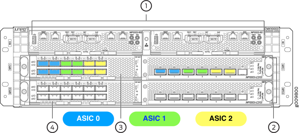
Each FPC provides three Eagle (EA) ASICs with ports from both PICs in the same FPC assigned to them. The diagram below shows the port assignments.

Each ASIC has four MACs* of which there are two types. Avoiding the terminology, let’s call these two types of MAC type-1 and type-2. Type-1 MACs support 100G-speed interfaces only, while type-2 MACs support all of the supported interface speeds: 100G, 40G, 4x10G and 4x1G, the latter two being channelised and requiring a fan-out cable to deliver each interface. The number of ports that each MAC type differs, too. Type-1 MACs support a single (100G) interface while type-2 MACs support a single 100G, or three 40G, or 12 10G, or 12 1G interfaces. The four MACs provided by each ASIC are in pairs: two type-1 MACs are available, as are two type-2 MACs.

So for each port group as shown above there are four MACs, two of type-1 and two of type-2. Interfaces are assigned to MACs in the following manner:

  1. The first two 100G interfaces are assigned to the two type-1 MACs
  2. Further 100G interfaces are assigned to the the type-2 MACs, one interface per MAC. Therefore if four 100G interfaces are configured in a port group no further interfaces are possible (all four MACs have been used)
  3. If any type-2 MACs are available each one can provide three 40G interfaces (or three 4x10G or three 4x1G).

One other consideration to this is the pic-mode. Each FPC operates in one of two modes: pic-mode and port-mode. I believe both PICs in an FPC must be in the same mode. In pic-mode, each port on a given PIC operates at the same speed and ports within the same group on different PICs can belong so the same MAC. In port-mode port speeds are independent, however ports on different PICs CANNOT belong to the same MAC.

MX10003 PFE Eagle ASIC MACs

In pic-mode the following configuration for a given port group is possible:

  1. PIC 0, ports 0 and 1 running at 40G (or 4×10 or 4×1). These consume two of the three 40G interfaces that one of the two type-2 MACs provides. There is now a single 40G port available on the first type-2 MAC, and three available on the second type-2 MAC.
  2. PIC 1, ports 0 – 3 running at 40G (or 4×10 or 4×1). Port 0 consumes the last interface on the first type-2 MAC, while port 1 -3 fully consume the second type-2 MAC.
  3. Both type-1 MACs are available and can be used for 0, 1 or 2 100G interfaces.

Note that the allocations above, PIC permitting, can be shuffled around.

In port-mode, however, the above configuration is not possible. This is due to the limitation that MACs cannot be shared between PICs in port-mode:

  1. PIC 0, ports 0 and 1 running at 40G. Two of the three 40G interfaces on the type-2 MAC are now consumed, the third being unavailable to PIC 1 (and therefore wasted). The remaining type-2 MAC can provide three 40G interfaces.
  2. PIC 1, ports 0 – 2 running at 40G. The second type-2 MAC is now fully used.
  3. Both type-1 MACs are available and can be used for 0, 1 or 2 100G interfaces.
  4. The sixth port cannot be used.

Juniper helpfully hides this complexity in a port checker tool (https://apps.juniper.net/home/port-checker/index.html) but hopefully the information above helps inform what happens in the background. The information in this post is mostly from https://kb.juniper.net/InfoCenter/index?page=content&id=KB35254&cat=MX10003&actp=LIST.

*I’m not sure what this initialism is short for.

Posted in Uncategorized | Tagged | Leave a comment

Cisco WLC, MAC authentication and Passthrough WebAuth

While Passthrough WebAuth upon MAC authentication failure is not supported on Cisco WLCs, it is easy to workaround this by doing the following.

The first step is to create a user to be used as a dummy account that the web-form will silently submit when the user agrees. This user should be created depending on where you authentication happens (radius or local).

The second step is to modify the passthrough HTML file (login.html, for example) to include a hidden <div> that contains the dummy user’s login details:

<div id="hiddenForm" style="display: none;">
<h4 align=center><font color="#000000">Username<input type="TEXT" name="username" SIZE="25" MAXLENGTH="63" VALUE="webauthdummy"></font></h4>
<h4 align=center><font color="#000000">Password<input type="Password" name="password" SIZE="25" MAXLENGTH="63" VALUE="webauthdummy"></font></h4>
</div>

Just make sure the above is within the <form> block. The above can be simplified; I got lazy and just modified Cisco’s webauth examples.

<h4 align=center><font size="5" color="#000000"><input type="button" name="Submit" value="ACCEPT" class="button" onclick="submitAction();"></h4></font><p></p>

As above I also modified the submit button slightly to say “ACCEPT” as the passthrough form does.

And that’s it. You can now set the “On MAC Filter failure” when using the Web Policy Layer 3 Security feature.

Posted in Uncategorized | Leave a comment

FreeRADIUS, MySQL and Cisco WLC AAA Override

Here’s how to get AAA Override working on a Cisco WLC using FreeRadius backed with MySQL:

  • Enable AAA Override on the WLAN on the WLC
  • Create a Dynamic Interface on the WLC with a vLAN and IP address
  • Add the following to the radreply MySQL table:
idusernameattributeopvalue
nusernameTunnel-Type=VLAN
nusernameTunnel-Medium-Type=IEEE-802
nusernameTunnel-Private-Group-Id=vlanId
radreply table

The NAS (WLC) will receive these parameters in the Radius reply packet when user username authenticates and will place the user on the interface with the corresponding vLAN.

Posted in Uncategorized | Tagged , , , , , , | Leave a comment

Cisco password type 7 Vigenère cipher seed/keyword

If you were ever wondering what the seed (keyword) is for Cisco’s password encryption type 7 (which uses the Vigenère cipher), in ASCII it’s:

dsfd;kfoA,.iyewrkldJKDHSUBsgvca69834ncxv9873254k;fg87

or in hex:

0x64, 0x73, 0x66, 0x64, 0x3b, 0x6b, 0x66, 0x6f, 0x41, 0x2c, 0x2e,
0x69, 0x79, 0x65, 0x77, 0x72, 0x6b, 0x6c, 0x64, 0x4a, 0x4b, 0x44,
0x48, 0x53, 0x55, 0x42, 0x73, 0x67, 0x76, 0x63, 0x61, 0x36, 0x39,
0x38, 0x33, 0x34, 0x6e, 0x63, 0x78, 0x76, 0x39, 0x38, 0x37, 0x33,
0x32, 0x35, 0x34, 0x6b, 0x3b, 0x66, 0x67, 0x38, 0x37

Posted in Uncategorized | Tagged , , | Leave a comment

Private vLANs

Having just implemented private vLANs on a Cisco 3750X switch I thought I’d share some findings.

A private vLAN configuration consists of a primary vLAN, zero or one isolated vLANs, and zero or more community vLANs.

When associated with each other, primary, isolated and community vLANs limit the switch’s forwarding scope for frames.

For a normal vLAN the forwarding scope comprises all ports to which that vLAN is assigned.

For a pvLAN the scope changes:

  • the primary vLAN is a normal vLAN with a normal scope; frames are forwarded to any or all ports to which the primary vLAN is assigned
  • an isolated vLAN is a point-to-multipoint topology, much like the Frame Relay NBMA, where the scope is limited to a single port to which the isolated vLAN is assigned and all associated primary vLAN ports
  • a community vLAN’s scope is a hybrid of that of primary and isolated vLANs; it comprises all ports to which the community vLAN is assigned and all associated primary vLAN ports

Treatment of broadcast and unknown destination frames received on a given port is as follows:

  • primary vLAN: frames are forwarded to:
    • all other ports in the primary vLAN, all ports in the isolated vLAN, and all ports in all community vLANs
  • isolated vLAN: frames are forward to:
    • all ports in the primary vLAN, while having their vLAN translated to the primary vLAN number
  • community vLANs: frames are forwarded to:
    • all ports in the same community vLAN and all ports in the primary vLAN, again having their vLAN translated to the primary vLAN number

Another way to look at private vLANs is that they provide vLAN translation on ports depending on which way frames are flowing:

From/ToPrimaryIsolatedCommunity
PrimaryNo translationP->IP->C
IsolatedI->PNot permittedNot permitted
CommunityC->PNot permittedNo translation
pvLAN translation

You can see that ports, regardless of their assigned pvLAN type, receive frames with their own vLAN id.

An interesting consideration with pvLANs is with layer 3 SVIs and pvLAN trunks with a router connected. If there is no IP ACL on the SVI/router port denying such traffic, any host, regardless of the vLAN type assigned to its port, can reach any other host in the same private vLAN configuration, simply by creating a static ARP entry where the destination host’s IP is mapped to the SVI/router port’s MAC address.

This is because any host can reach a router on a primary vLAN (using its MAC address), which then is able to reach any other host within the pvLAN.

Posted in Uncategorized | Tagged , , , | Leave a comment

Using LetsEncrypt certificates with Cisco WLC WebAuth

Assuming you’ve got a nice fresh certificate from LetsEncrypt and are in the directory where it, your key, and the LE root certificate1 (TrustID X3) lives:

cat domain.com.cer ca.cer dst.cer > fullchain-plus-root.cer
openssl pkcs12 -export -in fullchain-plus-root.cer -inkey domain.com.key -out domain-fullchain-key.p12 -clcerts -passout pass:wlc
openssl pkcs12 -in domain-fullchain-key.p12 -out domain-fullchain-key.pem -passin pass:wlc -passout pass:wlc
cp -a domain-fullchain-key.pem /tftpboot/certs/
transfer download mode tftp
transfer download datatype webauthcert
transfer download serverip 
transfer download path /certs/
transfer download filename domain-fullchain-key.pem
transfer download certpassword wlc
debug pm pki enable
transfer download start

Check the logs to make sure the import was successful. If so you will be reminded to reboot. If so:

reset system
Posted in Uncategorized | Leave a comment

Cisco ACLs and the ‘established’ keyword

While writing software to convert Cisco ACLs to VyOS’s firewall syntax I got to wondering what the ‘established’ keyword meant on TCP ACLs. Although my Internet facing ACL is connected to CBAC (and therefore stateful), my inter-vLAN ACLs are stateless, and so the ‘established’ keyword comes up a lot. Additionally, I have yet to successfully get the VyOS stateful firewall working so I needed to convert the Cisco ‘established’ to the VyOS equivalent.

I wrote a script that called nmap with all 64 combinations of TCP flags and send the traffic from a host to a destination in another vLAN across my IOS router. The destination ran tcpdump to collect the data. Firstly the script ran without any access-list to verify that the destination saw all 64 packets, and secondly with an access-list with the ‘established’ keyword set.

The results were:

RSTRST,PSHRST,URGRST,PSH,URG
RST,FINRST,FIN,PSHRST,FIN,URGRST,FIN,PSH,URG
RST,ACKRST,ACK,PSHRST,ACK,URGRST,ACK,PSH,URG
RST,FIN,ACKRST,FIN,ACK,PSHRST,FIN,ACK,URGRST,FIN,ACK,PSH,URG
ACKACK,PSHACK,URGACK,PSH,URG
ACK,SYNACK,SYN,PSHACK,SYN,URGACK,SYN,PSH,URG
ACK,FINACK,FIN,PSHACK,FIN,URGACK,FIN,PSH,URG

Of 64 possible combinations 28 are permitted. Note that the second, third and fourth columns are the first column plus ‘PSH’, ‘URG’, and ‘PSH,URG’

The table can be summarised as:

  • ‘RST’ with all flags except ‘SYN’ (16 combinations)
  • ‘ACK’, ‘ACK,SYN’, ‘ACK,FIN’ with ‘PSH’,’URG’, and ‘PSH,URG’
Posted in Uncategorized | Leave a comment